Why a bend changes the flat pattern
A bent sheet metal part cannot usually be laid out by adding its finished outside dimensions. Material on the outside of a bend stretches, material on the inside compresses, and a layer between them changes length relatively little. That layer is called the neutral axis. Bend allowance estimates the length of material taken up by the curved portion, so a flat blank can be cut to produce the intended finished dimensions.
A common planning formula is bend allowance = bend angle in radians × (inside bend radius + K-factor × material thickness). The K-factor describes the neutral axis position as a fraction of the thickness, measured from the inside of the bend. It is not a universal property of a metal: the bend method, tooling, radius and material condition can all affect the result. For repeat work, a measured allowance from a representative test bend is more useful than an assumed value.
Bend allowance and bend deduction are related but not interchangeable. Bend deduction is used when a flat length is calculated from the sum of outside flange dimensions; bend allowance is used when adding straight lengths measured to the bend tangencies. Mixing those dimensioning methods can produce a blank that is consistently too long or too short, even when the arithmetic looks correct.
Plan around the actual bend method
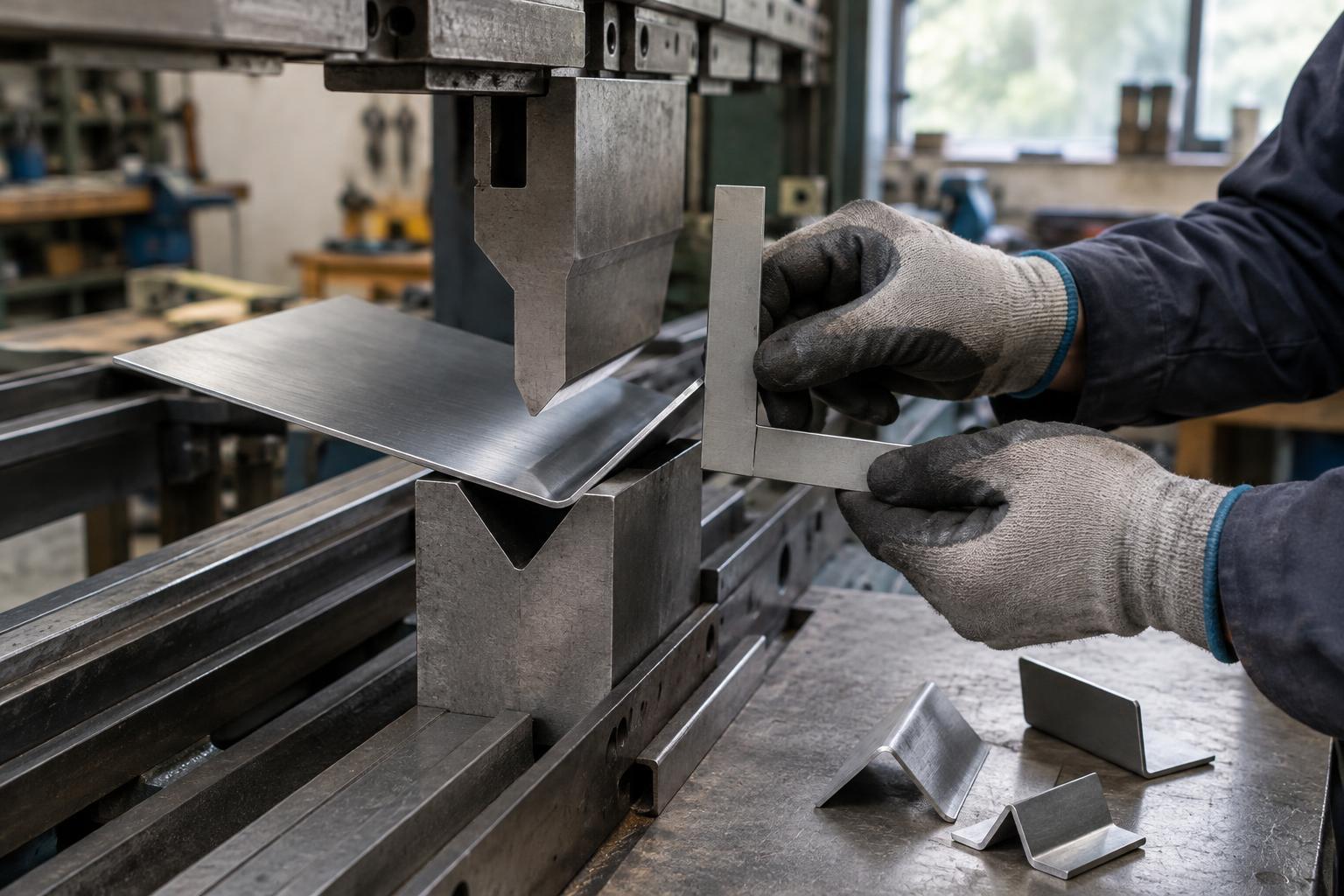
Air bending, bottoming and coining do not form a bend in the same way. In air bending, the punch presses the sheet into the die opening without fully seating it against the die. The resulting inside radius depends partly on the tooling and material, so it may differ from the punch tip radius. A flat pattern based on a different bend method can therefore miss the target even if the nominal thickness is unchanged.
Before cutting a batch, identify the material grade and condition, confirm its thickness, and record the punch, die opening and intended bend direction. Check whether the drawing specifies an inside radius, outside dimensions or a developed flat length. For parts with several bends, establish a bend sequence as well: an early flange may block access to the tooling or make a later bend difficult to gauge.
Account for springback
After a forming load is removed, some elastic deformation recovers. This springback opens the bend slightly, leaving a final angle different from the angle reached under the punch. Its size varies with material, thickness, bend radius and forming method. The direction of the sheet’s grain may also matter for some materials, particularly when a tight bend is planned.
Operators commonly compensate by bending past the desired final angle, then checking the part after release. The required overbend should be established with a test piece made from the intended stock and tooling, rather than copied uncritically from another job. Measure the relaxed part consistently; checking an angle while the sheet is still clamped can hide the difference that matters in the finished component.
A tighter bend is not always a better solution to springback. Forcing a small radius can increase the risk of cracking or marking the surface. If the angle is difficult to hold, review the radius, tooling and material specification alongside the overbend setting.
Catch setup errors before they multiply
A wrong backgauge position is a straightforward cause of an incorrect flange length. Less obvious problems include gauging against a burr, placing the blank against the wrong stop, or measuring from the wrong side of an asymmetric part. Marking the first blank’s orientation and comparing it with the drawing can prevent a mirrored or reversed bend.
Tool alignment and seating matter too. A poorly seated punch or die, damaged tooling, or debris beneath a tool can affect the bend along its length. On longer parts, angle variation from one end to the other may call for a check of machine setup and deflection compensation rather than repeated changes to the programmed angle. Confirm that the selected tooling provides clearance for existing flanges and nearby features.
Treat the first acceptable piece as a reference, not as proof that every subsequent piece will match. Check flange lengths, inside radius where relevant, final angle and visible surface condition. If results drift, inspect stock consistency, gauging and tooling before changing several settings at once.
Turn test bends into reusable knowledge
A short setup record can make future work more predictable. Note the material specification and measured thickness, tooling, die opening, bend direction, target dimensions, flat length and settings used. Record the measured result after springback, including any adjustment that brought the part into tolerance.
For a new design, leave room for verification before committing to a full batch. A small bend coupon can help establish an allowance and final angle; a complete first article then tests the bend sequence and feature locations. The aim is not to eliminate every adjustment, but to make each adjustment traceable so the next setup begins with evidence rather than a guess.